Linear Dimension Tool
The Linear Dimension Tool can be selected to draw a linear dimension line. Use a Click/Drag combination to draw the linear dimension line from a set starting point to a desired end point and then release the click to complete the drawing action.

How to Alter Dimension Line Size, Angle, and Position
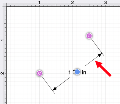
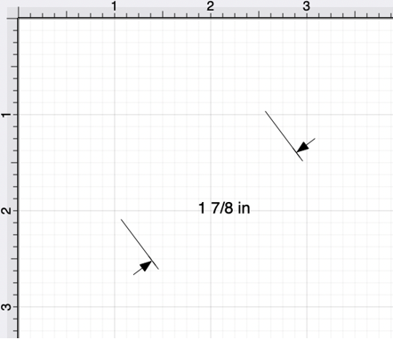
To alter the length or angle of a linear dimension line, click and drag using one of the connection handles on each end of the dimension line.
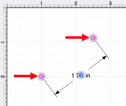
Do not release the click until the end of the dimension line is in the desired location. In the example below, the right connection point has been moved down and to the left.
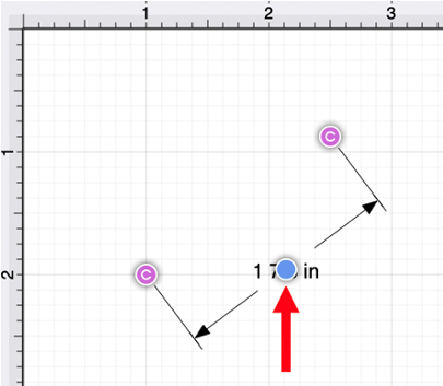
Click and Drag on the blue bounds handle to change the position of the dimension line between the connection handles.
Click and Drag on the dimension line to change its position within the Drawing Canvas.
How to Alter the Arrowhead Locations
The arrowhead locations within a linear dimension line can be located on the inside or outside.
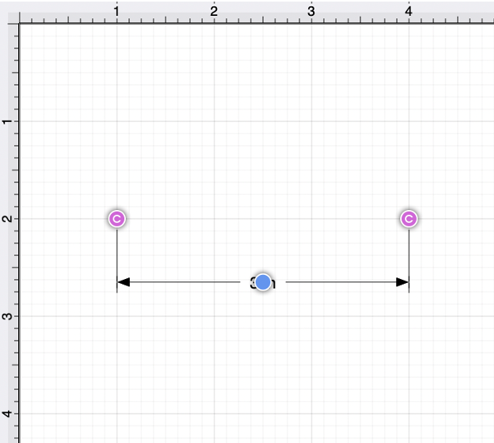
When located on the inside, a dimension line will appear, as shown below. This is the default selection.
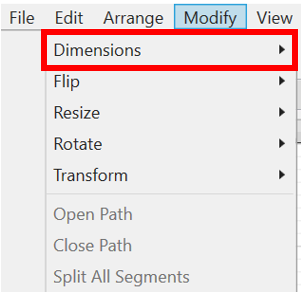
To change the arrowhead location to the outside for a selected dimension line, click on the Modify Menu and click on the Dimensions Submenu.
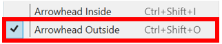
Next, select the Arrowhead Outside option to change the arrowhead location to outside. A checkmark will be present for the currently enabled arrowhead option.
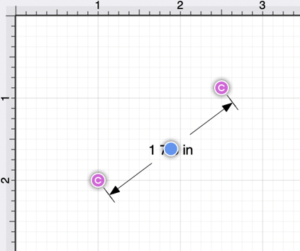
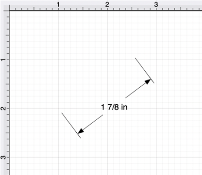
The linear dimension line will appear as shown below when arrowheads are on the outside.
How to Connect a Linear Dimension Line to Images/Figures
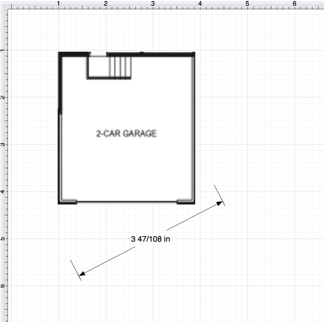
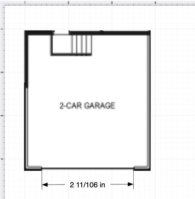
For this example, the Linear Dimension Line will be connected to two points within a simple garage floor plan image. The image and Linear Dimension Line have already been added to the drawing, as shown below.
Note: A linear dimension line can also be connected to two points on a figure or two separate figures when it is drawn.
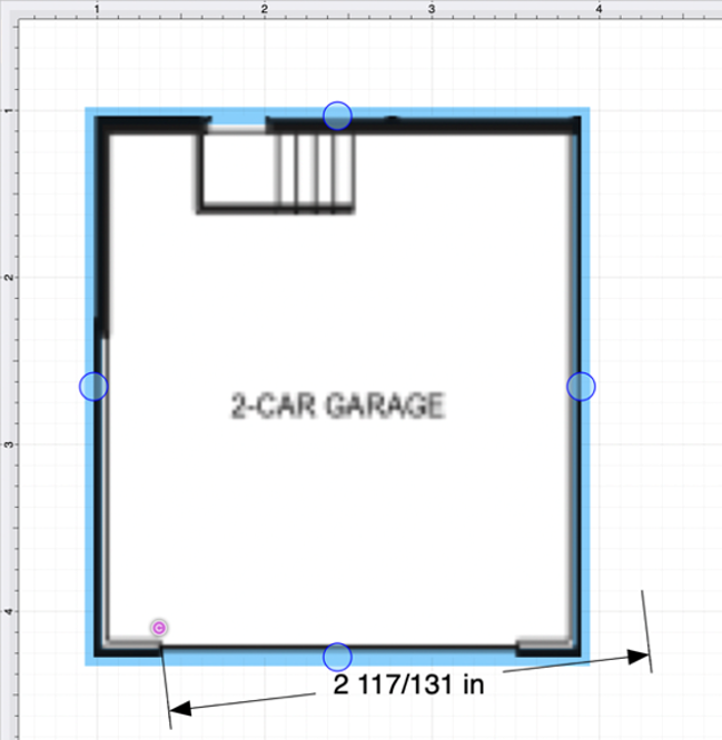
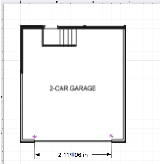
Perform a Click/Drag action on a connection handle within the dimension line to connect it to a point within a figure.
For more control over the position of each end of the dimension line, disable the Snap to Grid and/or the Snap to Lines options. A Shift/Click action can also be performed when moving each connection handle.
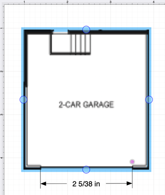
Perform this action again for the second connection handle within the dimension line.
Note: A Linear Dimension Line can also be drawn between two points on any figure or from one point on a figure to a point on another figure.
Using the Scale Attached… option The Linear Dimension Tool can be paired with the Scale Attached… option within the Modify Menu to scale an image, such as a floor plan, to match the grid and trace or perform other actions within the drawing “at scale.”
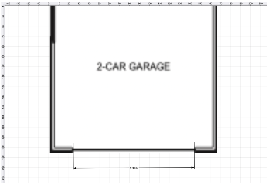
For this example, a simple garage floor plan image will be used to demonstrate the Scale Attached… option. The Linear Dimension Line has been connected to each end of the garage opening, as shown below.
Step 1: Click on the Linear Dimension Line to select it within the drawing.
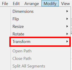
Step 2: Click on Modify Menu and click on the Transform Submenu.
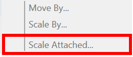
Step 3: Select the Scale Attached… option
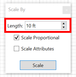
Step 4: Change the linear dimension line length by clicking on the Length field and using the keyboard to enter a new value.
The “up“ and “down” buttons can also be used to increase or decrease the Length value by 1.
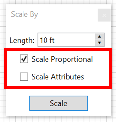
Step 5: Next, use the checkboxes to enable or disable the Scale Proportional and Scale Attributes options before scaling the image or figure.
-
Scale Proportional - Scale the image up to match the grid based on the entered dimension line length.
-
Scale Attributes - Scale the attributes (stroke, text, etc.) based on the entered dimension line length.
Step 6: Once finished, click on Scale within the pop-up window.
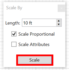
Note: If the Scale Attributes option is disabled, then Attributes will not be scaled.