How to Resize an Image to Scale
The linear, horizontal distance, and vertical distance dimension tools can be used to add a dimension line to a floor plan or other image and scale that image based on an entered value. Once scaled, the opacity can be changed to perform tracing on the floor plan image.
The step-by-step example is shown below:
Step 1: Insert the Floor Plan Image into the Drawing
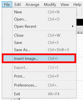
To insert the floor plan image into your drawing, click on the File Menu. Then click on the Insert Image… option.
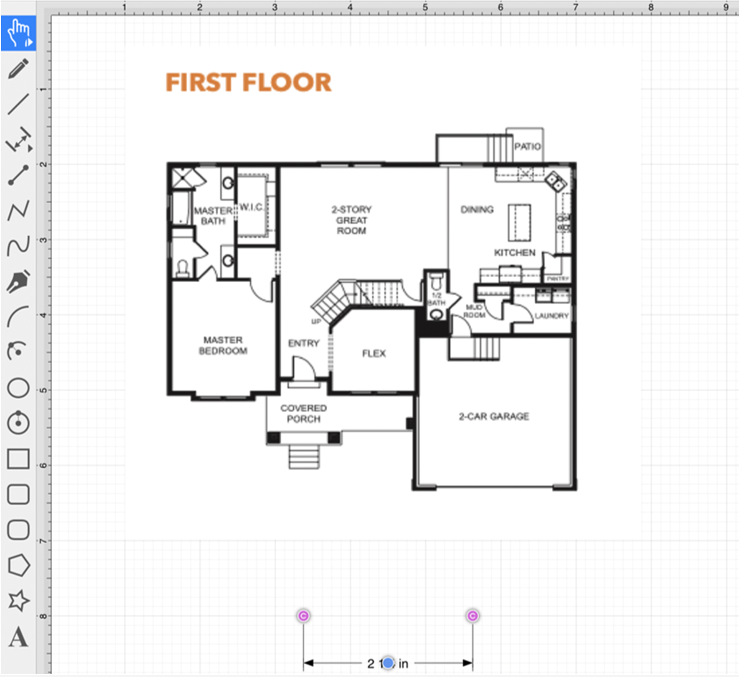
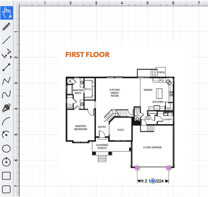
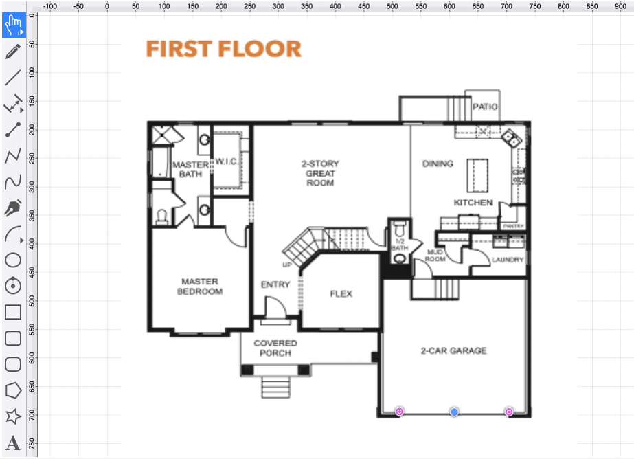
The floor plan image has been inserted into the drawing and is shown below:
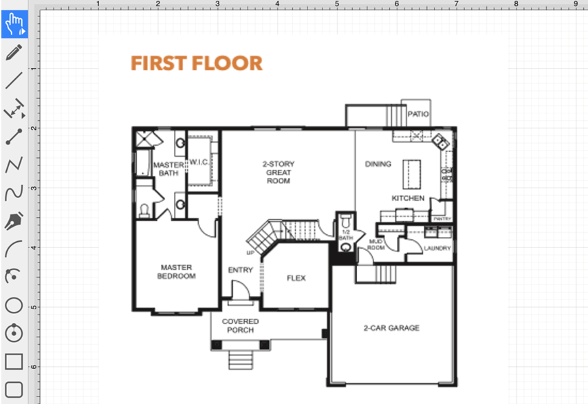
Note: For step-by-step instructions, please see: Inserting Images into Drawings.
Step 2: Draw a Dimension Line
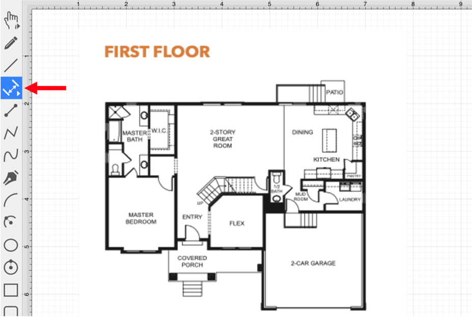
Next, draw a dimension line within the drawing. For this example, the Linear Dimension Tool will be used.
Click within the Drawing Toolbar to select the Linear Dimension Tool.
Next, draw a dimension line below the floor plan image.
Step 3: Disable the “Snap to Grid” Option
This option will need to be disabled so that the connection points for the dimension line can be dragged to a desired location within the floor plan image.
To disable this option, click on the View Menu and then click on the Snapping Submenu.
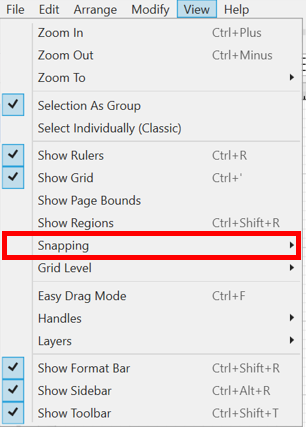
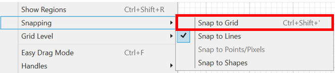
Next, click on Snap to Grid to disable the option. It will not have a checkmark when disabled.
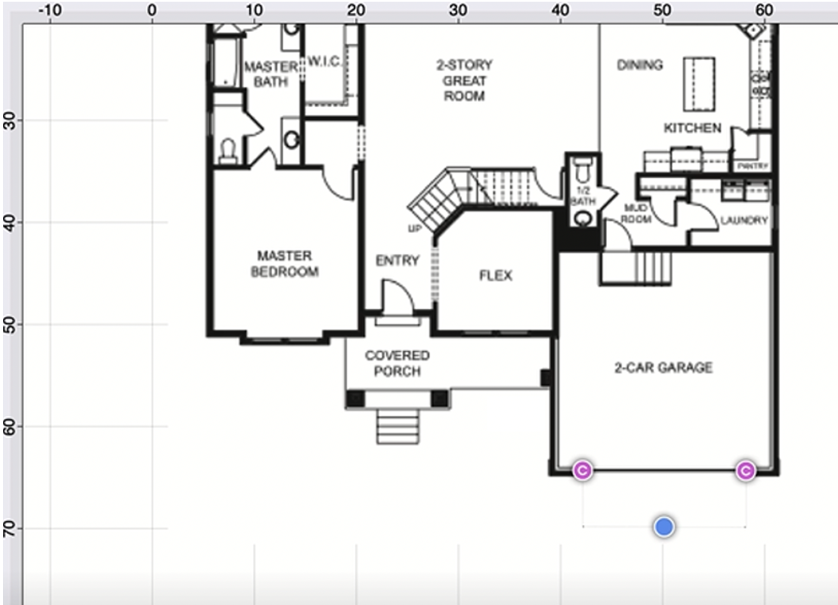
Step 4: Drag the Connection Points to a Specific Location within the Floor Plan
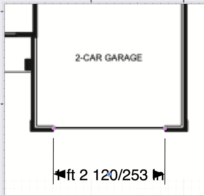
After the Snap to Grid option has been disabled, you will be able to drag each connection point on the dimension line to a desired location within the floor plan.
For the first connection point, use the Shift Key and a Click/Drag action to move it to the desired location on the floor plan.
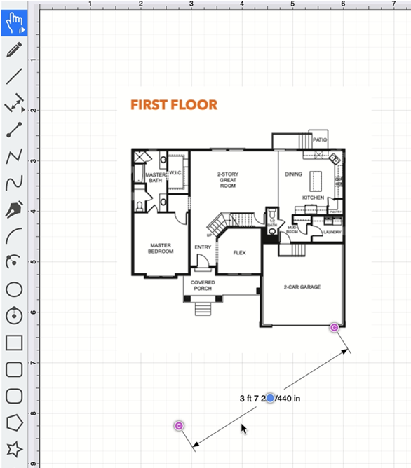
For the second connection point, use the Shift Key and a Click/Drag action again to move it to the desired location on the floor plan.
Tip: You can zoom in on a specific location within the floor plan to be more precise when changing the dimension line connection point locations.
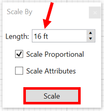
Step 5: Use the Scale Attached Option
The Scale Attached option can be used to scale the drawing based on an entered scale value (e.g., 10 ft).
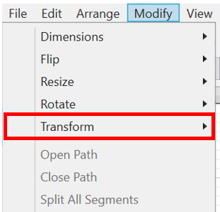
Click on the Modify Menu and click on the Transform Submenu.
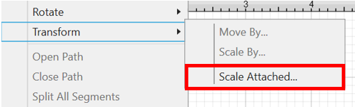
Next, click on the Scale Attached… option.
Enter a new Length value. For this example, “16 ft” will be entered. The image will scale based on the entered length value.
Step 6: Change the Dimension Line Font Size
Select the Dimension Line and then click and drag on the bounds handle to drag the handle downward.
Increase the font size so that the dimension information is viewable for the location the dimension line represents.

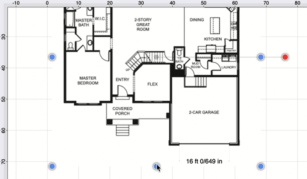
After the font size has been changed, the dimension information will be more visible, as shown below:
Step 7: Change the Opacity for Tracing
Select the image and select the Shadow and Opacity Tab in the Sidebar.
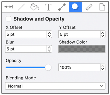
Click and drag on the opacity slider or use the “up” and “down” buttons to change the opacity value.
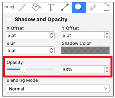
The image will appear as shown below:
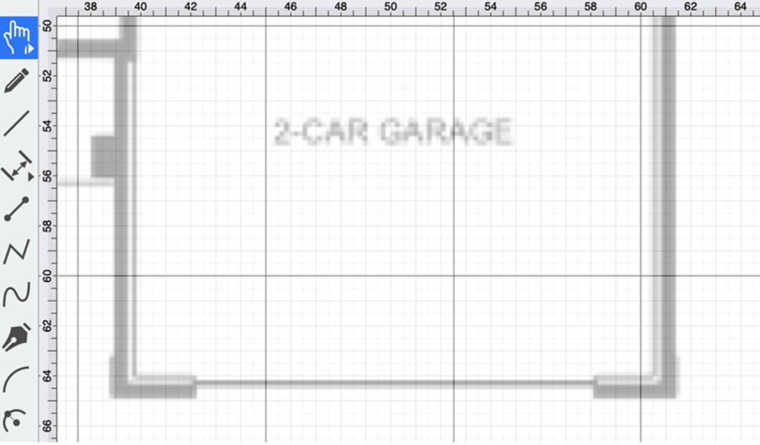
Completed Example
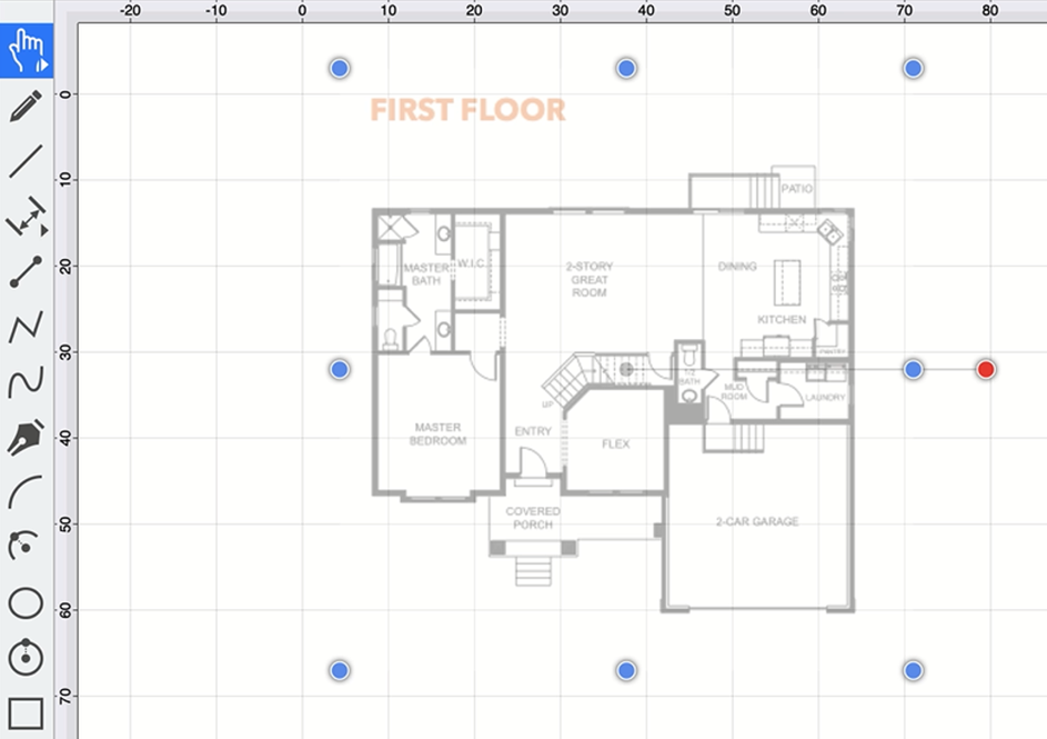
The floor plan can optionally be lined up to specific points on the gridline, as shown in the image below:
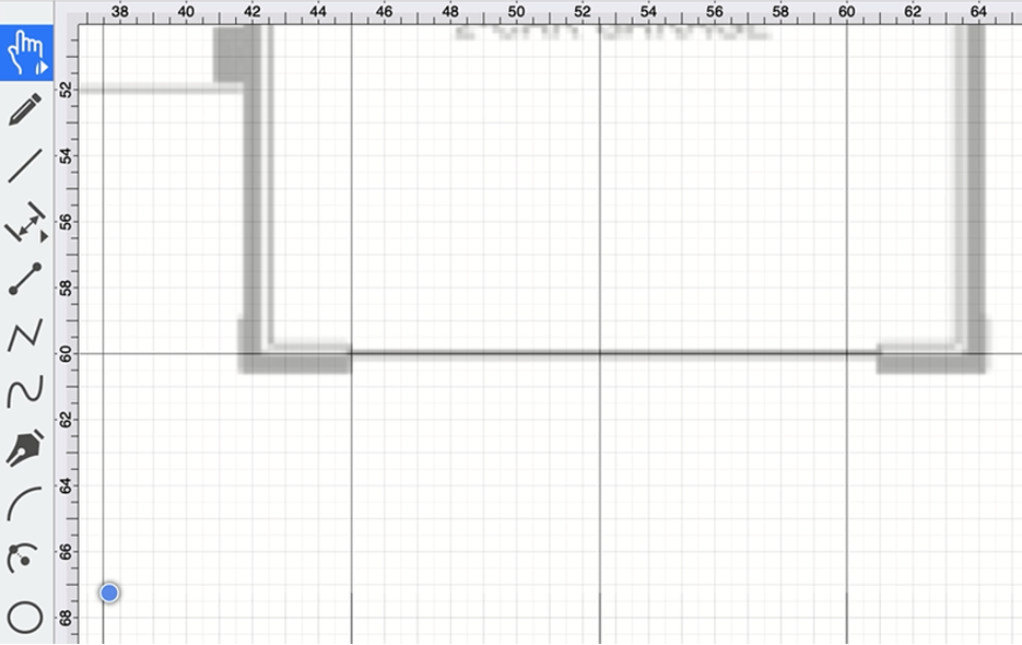
Once finished, zoom out to see the entire floor plan and perform any needed tracing activities.